The 2018 version of the SAE J3068 standard (Edition 1) includes a control pilot circuit identical to SAE J1772 (https://en.wikipedia.org/wiki/SAE_J1772#Signaling) with the addition of LIN transceivers on each side. This circuit leaves out an important consideration for backward compatibility.
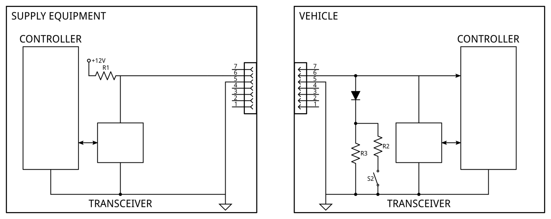
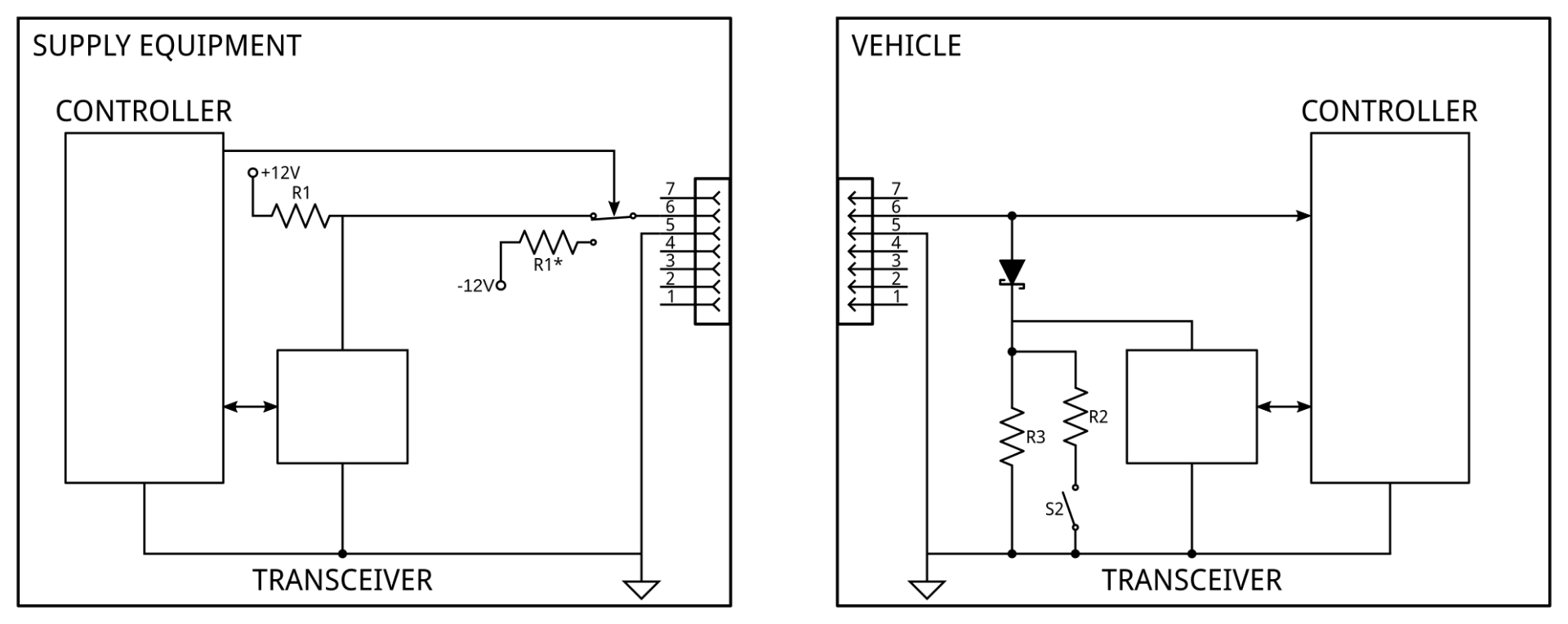
Commercially available LIN transceivers (e.g. TI SN65HVDA100-Q1) include a 30k pull-up to the bus voltage (nominally intended to be the vehicle’s battery voltage). While this pull-up is not necessary for correct operation in most cases as the LIN standard requires an external 1k pull-up, it can simplify some configurations and make operation more predictable. Unfortunately, this pull-up significantly loads the PWM signal’s negative side, which can be interpreted by some implementations as an unsafe connection. Therefore, the transceiver must be disconnected from the bus or disabled (most, if not all, commercial LIN transceivers disconnect this pull-up when disabled to save power. However, some may still load the bus to a lesser degree even when disabled) during PWM signaling. The upcoming version of the standard will introduce some changes to the EV side of the circuit to remove this requirement (on that side). The diode is replaced with a Schottky barrier diode (link) with a significantly reduced (and more stable over temperature variation etc.) forward voltage. The values of the load resistors are then changed to produce the correct voltages. With these changes, the LIN transceiver can be moved to the other side of the diode while still pulling the bus down sufficiently for reliable communication. The transceiver cannot, unfortunately, be put behind a separate diode without blocking incoming data.
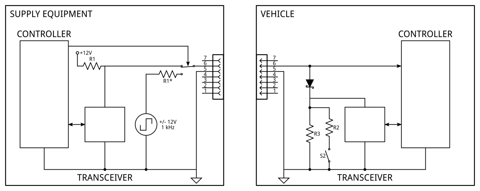
A corresponding change can be made to the EVSE side to achieve seamless switching between LIN and PWM. In practice, many implementations will produce the PWM signal with an analog switch (e.g. Vishay DG470) controlled by a microcontroller. This switch can then be left in the high state to provide the LIN bus voltage instead of requiring a separate switch between the PWM generator and the LIN bus. If the 1k pullup is moved to the other side of the analog switch (and split into two, see diagram), the transceiver can also be moved, removing it from the circuit during the negative side of the PWM cycle.